Fischertechnik Demonstrator - Digital Twins for Manufacturing Systems
Didier Vojtisek (IRISA, Inria)
Summary
This use case is a research demonstrator for the engineering of digital twins of production systems. The physical platform is a modular Fischertechnik manufacturing line made up of six stations - automated warehouse, two vacuum-gripper robots, conveyor belt, multi-function processing station (turntable, oven, gripper) and color-sorting line - controlled by three RevPi PLCs (Plc-01 to Plc-03) via an Ethernet switch and the MQTT protocol.
A shared reference architecture is instantiated for three operational scenarios of increasing complexity. It distinguishes the DT’s core components (DT gateway, synchronizer, engine, data and model managers) from value-added services (monitoring, analysis, planning, notification). This architecture is implemented through model-driven code generation (MontiGem) from MontiArc and SysMLv2 models.
The main objective is to show how a single DT infrastructure can be reused for multiple, concurrent operational concerns, and to establish a basis for comparison for evaluating digital twin engineering approaches.
This work stems from the MBDO project (Model-Based DevOps, ANR + DFG), bringing together IRISA (Université de Rennes), RWTH Aachen University and Manufacturing Units (ISW) of Stuttgart University.
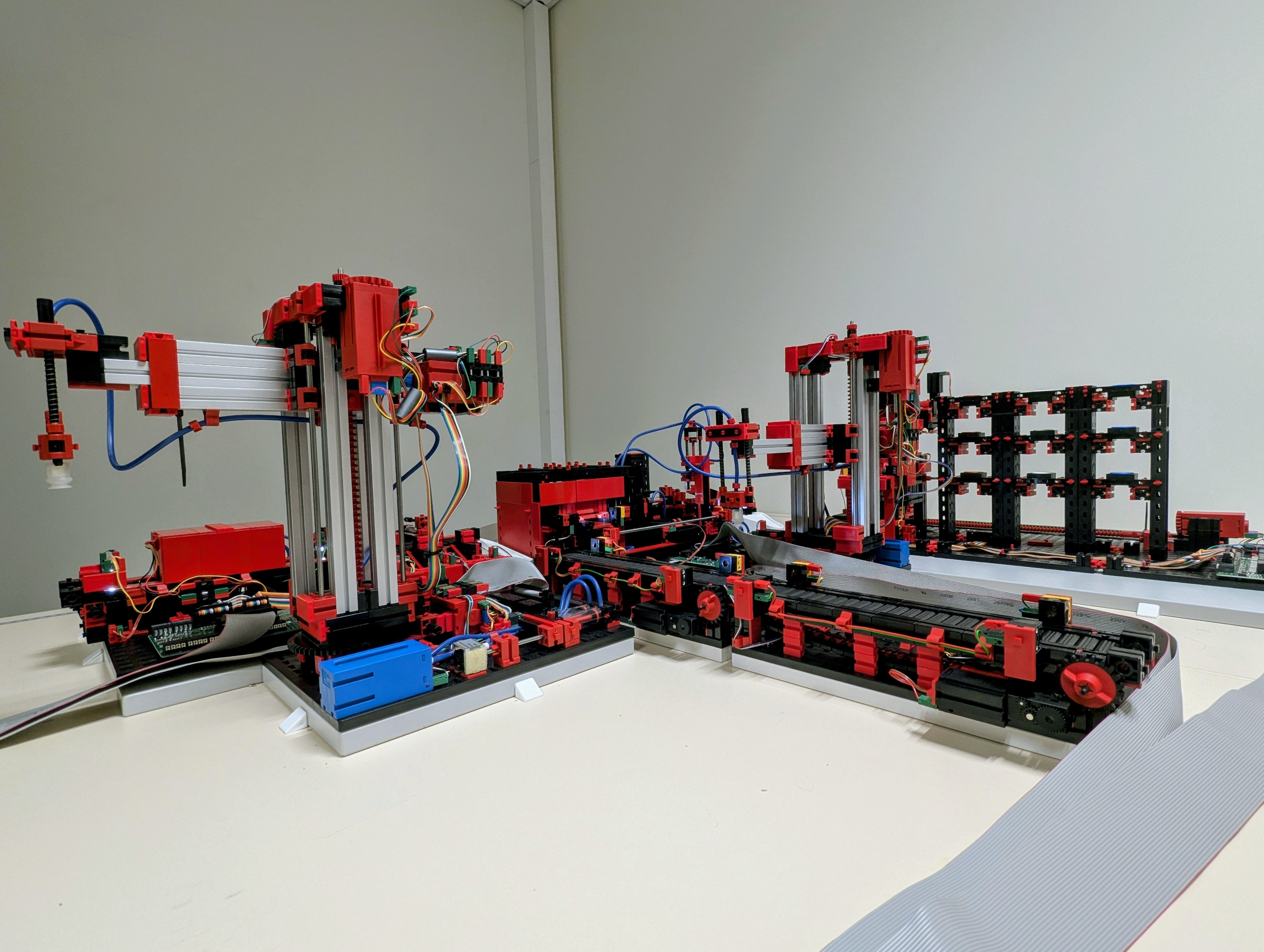
Physical demonstrator - Fischertechnik modular production line.
Functional Description
Users
- A production operator - supervises the line in real time, receives alerts and applies recommended procedures
- A plant manager - tracks aggregated energy consumption, drives production targets and avoids shutdowns from capacity overruns
- A maintenance engineer - detects abnormal machine behavior, schedules preventive interventions and confirms recoveries
- A production planner - coordinates maintenance windows with throughput targets and minimizes unplanned downtime
- A DT engineering researcher - uses the demonstrator as a reference platform to experiment with and compare DT design approaches
Functional Requirements
-
Describe + Monitor · An operator wants to visualize in real time the energy consumption of each machine and the aggregated consumption to detect anomalies and plan next steps. Metric: interactive dashboard, continuous refresh, alert when aggregated consumption approaches or exceeds the smart-grid limit.
-
Diagnose + Control · A plant manager wants to be notified if total production consumption exceeds the limit set by the smart grid to avoid a forced production shutdown. Metric: notification delay < update cadence; limit-minus-consumption gap computed and archived.
-
Diagnose + Optimize · A maintenance engineer wants the DT to automatically detect disruptions to the nominal production trajectory and select an alternative trajectory to maintain throughput without systematic manual intervention. Metric: disruption detection rate, recovery time, reduction in unplanned downtime.
-
Predict + Control · A maintenance engineer wants the DT to monitor motor speed deviations under different loads and propose an intervention before failure to avoid unplanned stoppages. Metric: anomaly detected before physical failure; MTBF and MTTR indicators computed automatically.
Digital Twin Characterization
Grid based on the unified framework by Gil et al. (2024) - 21 characteristics.
MC1 - System under study
The system under study is a modular Fischertechnik production-system demonstrator comprising an automated warehouse (High-Bay Warehouse, HBW), two vacuum-gripper robots (Vacuum Gripper Robots, VGR01 and VGR02), a conveyor belt (Conveyor Belt, CB), a multi-function processing station (Multi-Processing Station, MPS) and a sorting line (Sorting Line, SL). The equipment is controlled by RevPi controllers.
The system handles tokens of different colors. The HBW stores parts and makes them available on its integrated conveyor. The two VGRs handle transfer of parts between the various modules. The MPS performs a processing sequence that notably includes a furnace, a turntable, a vacuum-gripper transport mechanism and an output conveyor. The sorting line classifies parts by color and directs them to different outputs.
The modules are combined according to different production scenarios. The control system and the interfaces with the controllers depend on the scenario considered and may in particular include a SCADA system.
MC2 - Physical action components
The actionable physical components of the system include the electric motors as well as the pneumatic actuators available on the various production modules. The pneumatic actuators are notably controlled via a compressor and valves. These actuators are driven by the PLCs to which the equipment is connected. Depending on the scenario considered, the digital twin can send commands to these PLCs, either directly or via the installation’s control system, at different levels of abstraction.
At the elementary level, it can command individual actions, such as moving a robot axis, rotating a mechanism, moving a conveyor or activating a pneumatic actuator. At the functional level, it can also trigger sequences composed of several elementary actions. For example, a VGR can receive a pick-move-place command for a part, while the MPS can execute a sequence combining the insertion of a part into the furnace, its transfer to the turntable, its processing and its ejection onto the output conveyor.
Some scenarios may also include actions performed by a human operator. The digital twin can then generate a request for intervention addressed to the operator, who performs the required action on the physical system.
MC3 - Physical sensing components
The sensing components include the encoders and pulse counters of the motorized axes, the reference switches and the light barriers integrated into the various stations. The encoders provide information on the position and movement of the axes, while the reference switches provide reference positions. The light barriers detect the presence and passage of parts at transfer and output points. The sorting line also has a color sensor to determine the color of the parts.
The state of the equipment’s actuators - notably motors, valves and compressors - is also observable by the control system at regular intervals. Energy-consumption measurements can additionally be acquired at the equipment level using instrumentation mechanisms suited to the installation.
Data from these sensing mechanisms is transmitted by the control systems and can be made available to the digital twin. Some information, such as axis position or speed, can also be derived from the raw sensing signals.
MC4 - Physical → virtual interaction
Data from the physical system is transmitted by the PLCs to the MQTT broker, which is the communication mechanism between the physical system and the digital twin. The DigitalTwin-Gateway receives the MQTT messages and filters, transforms or aggregates the data before forwarding it to the digital twin. Depending on their nature and use, some data may thus be kept, aggregated or discarded.
For data produced by the PLCs, the publication frequency of the raw data depends on the acquisition and processing frequency configured in the PLCs. The effective update frequency of the digital twin may therefore differ from this raw frequency, particularly when the data is filtered or aggregated by the gateway.
MC5 - Virtual → physical interaction
The outputs generated by the digital twin are transmitted to the installation’s control system. Depending on the scenario considered, the digital twin can either substitute for the SCADA system to directly control the equipment via the available communication interfaces, or interact with the SCADA backend by substituting for its operator interface.
The available commands correspond to the actuation capabilities defined in MC2. They can be issued at different levels of abstraction, from elementary actions on the actuators to functional operations composed of several actions. For example, the digital twin can request the movement of an axis, the activation of an actuator or the movement of a conveyor, or trigger a functional operation such as picking, moving and placing a part, or a complete processing sequence at the multi-function station.
When the digital twin interacts with the SCADA backend, the latter can also provide predefined execution scenarios. These scenarios, defined manually or generated from a model, encapsulate complex sequences of actions and can be triggered by the digital twin as higher-level operations.
MC6 - DT services
The digital twin is designed to address at least 3 use cases - energy monitoring, flexible replanning and predictive maintenance - which combine the following services:
- Data acquisition and contextualization
- real-time data collection;
- synchronization with the DT;
- enrichment with context (model, scenario, history, etc.).
- Visualization and supervision
- visualization of the current state;
- dashboards;
- history consultation;
- notifications.
- Analysis
- computation of indicators (KPIs);
- aggregation;
- correlation between data;
- comparison of expected / observed behavior;
- drift or anomaly detection.
- Decision and optimization
- energy optimization;
- replanning;
- selection of alternative scenarios;
- recommendations.
- Control
- command execution;
- mission execution;
- interaction with SCADA;
- interaction with the operator.
MC7 - Time scale
Multi-temporal: event-driven (MQTT) for sensor acquisition and disruption detection (latency < machine cycle time), cyclic per part produced for contextual enrichment and motor anomaly detection (UC3), periodic for retrieving the grid limit (REST, UC1) and computing KPIs, long-term for historization and retrospective analysis (InfluxDB, PostgreSQL).
MC8 - Multiplicities
The three scenarios run in parallel on the same shared DT infrastructure (gateway, synchronizer, engine, data manager). Each scenario instantiates its own services (Shadow Aggregator, Replanning Service, Maintenance Planner), which operate independently but share access to the same digital shadows. This multi-service architecture illustrates the federation of DTs on a single physical system.
MC9 - Lifecycle phases
The digital twin operates mainly during the operational (as-operated) phase of the production line, where it provides supervision, analysis and control of the physical system. It also relies on design models (as-designed), notably SysMLv2 and MontiArc models, which describe the system’s expected architecture and behavior and serve as a reference for analysis, validation and replanning.
MC10 - Models and data
Models
The digital models represent the structure, behavior and semantics of the physical system.
- SysMLv2 structural models: description of the equipment, its properties, ports, interfaces and the topology of the installation.
- Architectural models (MontiArc): description of the line’s functional architecture, its components, their interfaces and the flows between them. These models are notably used to generate parts of the digital twin.
- SysMLv2 behavioral models: description of the expected behaviors, production sequences and state machines used to track the evolution of the process and detect deviations.
- Asset Administration Shell (AAS): standardized representation of assets, their properties and associated metadata, used to contextualize the equipment and facilitate its integration.
Data
The data represents the current state, history and knowledge built from the operation of the system.
- Current system state: synchronized representation of the states of the equipment, parts and observed variables.
- History: time series of measurements, events and states collected during operation.
- Contextual data: production information, operating parameters, events, energy consumption, etc.
- Derived knowledge: baseline profiles, indicators, statistical or analytical models built from historical data and used for analysis, anomaly detection or decision support.
A particular feature of the Fischertechnik twin’s construction process is that data schemas are inferred as much as possible from the models in order to formalize the mapping.
MC11 - Tools and enablers
The development and execution of the digital twin rely on Model-Driven Engineering (MDE) technologies and on a software infrastructure ensuring integration with the physical system and the execution of the DT’s services.
- MDE technologies and tools - models are a central means of specifying the structure, behavior and processes associated with the production system. The platform relies notably on architectural modeling technologies such as MontiArc, on SysMLv2-based models to describe the structure and behavior of the systems, as well as on process-modeling formalisms such as BPMN where needed to represent and orchestrate workflows.
- MontiGem - model-driven generator used by some scenarios, allowing part of the digital twin application to be produced from models, notably the DT backend, data persistence and the DT frontend. Interfaces with external systems and specific behaviors can be added as hand-written code.
- Digital twin infrastructure - a set of software components providing the common functions required by the DT services, notably managing interfaces with the physical system, synchronization, data management, model management and service orchestration.
- DT communication interfaces - mechanisms for connecting the digital twin to the installation’s control systems. In the configuration studied, MQTT is used as the communication and data-aggregation infrastructure for data from the physical equipment before it is processed by the digital twin.
- Data and model managers - components providing the DT services with access to the digital models, operational data, history and derived knowledge, independently of the underlying storage mechanisms.
- AAS Manager - component allowing the DT services to access asset information and its metadata represented as Asset Administration Shells (AAS), and to use it to contextualize the equipment and its properties.
- Execution and integration environment - software components, notably developed in Java/Spring Boot, implementing the interfaces with external systems as well as the specific behaviors and services that are not automatically generated.
- Workflow Controller - orchestration component for coordinating processing sequences and decision loops involving data analysis, planning and action execution.
- Persistence mechanisms - InfluxDB is used for the persistence of time-series data and measurement series, while PostgreSQL is used for the relational and structured data required by the DT services.
MC12 - DT constellation
Physical system
    ↕ MQTT
DT Gateway (DT-MQTT Upstream/Downstream Interfaces)
    ↕
DT Engine (Controller + Service Manager + Synchronizer)
    ↓                   ↓              ↓
    ↓           Data Manager      Model Manager
    ↓           (InfluxDB +        (SysMLv2Parser +
    ↓            PostgreSQL)        AAS Manager)
    ↓
    Services
   ├── Monitoring & Visualization
   ├── Data Aggregation & Historization
   ├── Analysis & Anomaly Detection
   ├── Energy Management & Optimization
   ├── Planning & Replanning
   ├── Predictive Maintenance
   ├── Notification & Decision Support
   └── Execution & Control
The digital twin constellation is orchestrated by a DT engine that coordinates synchronization with the physical system, access to the models and data, and execution of the digital twin’s services. Data from the controllers and physical equipment is collected and aggregated via the gateway and the MQTT infrastructure, then integrated into the digital twin by the synchronizer. The Data Manager gives the services access to current and historical data, while the Model Manager gives access to the digital models and the associated semantic information. The Service Manager orchestrates the execution of the services and coordinates their interactions with the data, the models and the physical system.
MC13 - Twinning process and evolution
The development of the digital twin follows an iterative approach inspired by Model-Driven Engineering and DevOps. The physical system and its digital twin can be designed and co-evolved together. Design models describe the structure, behavior and expected properties of the system and can be used to generate or configure the digital twin’s software components.
After deployment, the data and events collected during operation make it possible to verify the system’s behavior, identify deviations or new requirements, and evolve the digital twin’s models, configurations and services. Changes can be introduced by designers during development phases, by operators during operation, or, where planned by the scenario, automatically from observed data and events.
The process thus forms a continuous loop between modeling, generation and integration, deployment, operation, observation and evolution. Changes to the physical system can lead to an evolution of the digital twin’s models and services, while analysis of the digital twin’s operation can lead to adaptations of the physical system, its controllers or its control architecture.
This approach thus enables the digital twin constellation and its services to evolve gradually, without imposing a fixed sequence of use cases. New models, services and integration mechanisms can be added according to the scenario’s needs and the evolution of the physical system.
The current implementation does not yet cover the whole of this loop, however. The modeling, generation, integration, deployment and operation mechanisms are available or being integrated, but the systematic use of operational data to automatically or semi-automatically evolve the system and digital-twin models remains a development objective.
MC14 - Fidelity and validity
The fidelity of the models making up the digital twin is adapted to the objectives of the scenario and the services provided. The platform does not assume the existence of a single, complete representation of the physical system: several models or specialized instances of the digital twin can represent different aspects of the system at different levels of detail. A service can thus use a behavioral or functional representation of the system without requiring a detailed geometric or topological representation, while other services can use more detailed models where necessary.
The validity of a representation is therefore assessed relative to its intended use and to the properties of the system it must reproduce or expose. Structural and behavioral models can be verified against the system’s expected properties and behaviors, while representations synchronized with the physical system are compared against the data and events observed during operation. Deviations between expected and observed behavior can thus be used to identify anomalies or inconsistencies.
The various models and representations can be combined, or be the subject of collaboration between several specialized instances of the digital twin. This approach limits the complexity and cost of representation to the information needed for the service concerned, while retaining the ability to progressively enrich the representation as new requirements emerge.
Explicit management of uncertainties and systematic quantification of representation errors are still aspects to be further developed. Current validation relies mainly on comparing the models and expected behaviors with the observed states of the physical system and the expected results of the usage scenarios. Where possible, the behavioral models used by the digital twin are derived from the models and specifications developed during the design phase, in line with the Model-Based DevOps approach. Validation thus notably involves checking the consistency between the behavior specified at design time, the behavior implemented in the digital twin and the behavior observed on the physical system.
MC15 - Technical connection
The technical connection between the physical system and the digital twin depends on the physical-system boundary chosen for the scenario considered. Data from the physical equipment is collected in a unified way via an MQTT infrastructure. The PLCs publish the available states and measurements, which are collected, filtered and aggregated by the gateway before being integrated into the digital twin.
Communication from the digital twin to the physical system, however, depends on the control architecture and the components included in the physical system considered. When the physical system is limited to the equipment and its PLCs, DT commands are transmitted to the controllers via the communication interfaces and control protocols specific to the installation, notably via dedicated TCP connections. MQTT is then not used as a generic mechanism for controlling the PLCs.
When SCADA is included within the physical-system boundary, the digital twin can interact with it at the level of its control interfaces. It can then substitute for the operator interface and invoke the operations exposed by the SCADA backend, notably via REST APIs or gRPC interfaces over WebSocket.
The web and service interfaces used for the digital twin’s applications and services notably include Spring REST APIs and push-notification mechanisms such as Server-Sent Events (SSE). REST interfaces can also be used to access external services, such as those providing energy information. The import/export mechanisms associated with AAS enable the exchange of asset metadata with external systems.
MC16 - Hosting / deployment
The reference deployment used for the experiments hosts the digital twin engine, its associated services and the data-management components on a central server. The digital twin’s functionalities are accessible through communication and service interfaces, notably a Spring-based web interface, as well as REST, gRPC and WebSocket interfaces.
The architecture does not, however, require all components to be hosted on the same machine. The various components of the constellation can be deployed in a distributed manner according to the constraints of the scenario and the infrastructure available. The MQTT broker, the databases or certain specific digital-twin services can thus be hosted on systems separate from the main server.
The reference deployment is currently used in laboratory and experimentation environments, notably at the partner sites.
MC17 - Insights and decision-making
The digital twin provides information and decision-support elements based on the synchronized representation of the physical system, its models and historical data.
Visualization makes it possible to inspect the current state of the system and the evolution of its components and processes. It can also provide a representation of expected states or planned trajectories, enabling the operator to understand the system’s behavior and visually identify any deviations.
Model- and data-based analysis makes it possible to compare observed behavior with expected behavior and to identify disruptions, anomalies or divergences. Historical and contextual data can be used to characterize these deviations, investigate their possible causes and estimate how they will evolve.
Planning and scenario analysis make it possible to compare alternative trajectories or strategies, notably for recovery after a disruption, operational optimization or planning a maintenance intervention. These analyses can be used to evaluate what-if scenarios before an action is selected.
The digital twin can also produce alerts, notifications and recommendations for operators and engineers. These outputs may concern a detected anomaly, a recommended maintenance action, a recovery strategy or an alternative plan. Depending on the scenario, a decision may be validated by a user before being transmitted to the control system for execution.
MC18 - Horizontal integration
The digital twin exchanges information with external systems independent of the production line and its DT infrastructure. In the energy-monitoring scenario, the digital twin periodically queries the REST interface of an external service representing the energy grid to retrieve the available consumption limit. This information is then integrated into the digital twin’s data and combined with the line’s consumption measurements to compute the available energy budget.
The architecture also allows external services and systems to be integrated using interfaces suited to their role and communication protocol. The mechanisms associated with AAS can notably be used to exchange or interpret asset and context information in interoperable environments. The possibility of exchanging information with other digital twins or production systems can thus be envisaged, but interoperability with heterogeneous industrial infrastructures and the integration of several distributed DTs have not yet been evaluated in the demonstrator.
MC19 - Data ownership and privacy
The operational data produced by the physical system within the demonstrator - notably the states, measurements and events of the equipment - are considered freely usable within the context of the project.
Most of the models used by the digital twin are created within the project, notably the SysML and MontiCore models, and are released as open-source artifacts in accordance with the license terms applicable to the project.
Some external technical models and artifacts used as sources by specific digital-twin services may, however, be subject to intellectual-property and confidentiality restrictions. This is notably the case for some source models provided for generating 3D visualizations of the Fischertechnik equipment. These source models are subject to confidentiality agreements, and access to them is limited to the holders of the physical equipment concerned. These NDA-covered artifacts are an exception relative to the models developed within the project.
The software components and models developed within the MBDO project can be released separately from these proprietary artifacts. Tools or executables produced from source models subject to restrictions may also be distributable, subject to checking the contractual clauses and rights applicable to these derived artifacts. In particular, the possibility of redistributing a compiled tool that incorporates these models without redistributing the source models themselves must be confirmed against the applicable confidentiality agreements and license terms.
The architecture thus distinguishes between the operational data and the majority of the models and components developed within the project, which can be freely distributed under their licenses, and the external source models subject to access and redistribution restrictions.
MC20 - Standardization
The digital twin’s architecture and engineering rely on several standards and standardized technologies:
- ISO 23247 (Digital Twin framework for manufacturing) - used as a reference framework for structuring the description of the digital twin constellation and its interactions with the physical system;
- SysMLv2 (OMG) - used for the structural and behavioral modeling of the systems and their processes;
- MQTT 5.0 (OASIS) - used for collecting and distributing data from the controllers and physical equipment via a messaging infrastructure;
- Asset Administration Shell (AAS), based on the standards and specifications of the Industry 4.0 ecosystem - used for representing and exchanging metadata and contextual information about assets;
- BPMN (OMG) - used for modeling and orchestrating certain workflows and decision processes.
The engineering approach also relies on Model-Driven Engineering (MDE) technologies to transform models into software components and digital-twin infrastructure. The languages and models used in this approach are thus integrated into an engineering chain based on modeling technologies rather than treated as simple data formats.
The architecture is designed to allow additional industrial communication protocols to be added. Support for OPC UA (Open Platform Communications Unified Architecture) is notably envisaged as a future evolution for communication with industrial controllers and equipment.
MC21 - Security and safety
The demonstrator is based on a compact Fischertechnik installation whose mechanical components and energy levels greatly limit physical risks, including those associated with remote operations. At the various deployment sites, the digital twin runs within the local network dedicated to the Fischertechnik installation. Communications between the digital twin, the control systems and the physical equipment are thus confined to the installation’s local network infrastructure, which limits the system’s direct exposure to external networks.
The digital twin can nonetheless trigger actuation operations, notably in scenarios involving replanning or maintenance actions. It can also support operations requiring human intervention or validation before execution. This possibility provides a supervision mechanism for the control loop: certain decisions or actions can be submitted to an operator before being transmitted to the physical control system.
In the current demonstrator, the specific mechanisms for securing communications between the physical system and the digital twin - notably authentication, encryption and formal authorization management - are not yet comprehensively addressed. However, the digital twin’s access interfaces are exposed through the application architecture and its service interfaces, rather than through direct, uncontrolled access from outside.
Transposing this architecture to industrial equipment presenting risks to people would require additional security and safety mechanisms.
Operational scenarios
UC1 - Monitoring maximum energy consumption
The line is connected to a smart grid that dynamically sets a total power limit. The DT measures and logs the consumption of each machine, aggregates the process consumption, retrieves the grid limit in real time via REST, computes the residual budget and notifies the operator and the manager when consumption approaches or exceeds the limit.
Architecture: MontiArc C&C model → MontiGem → Backend (Spring Boot + PostgreSQL) + Frontend; Shadow Aggregator + Dashboard Service + Notification Service on the DT engine.
UC2 - Flexible replanning after a disruption
The DT continuously monitors the nominal progress of a part between stations. When a disruption is detected (expected progress not confirmed within the allotted time), it identifies the affected step and component, selects an alternative trajectory via SCADA, notifies the maintenance engineer and archives the decision for KPI analysis (MTTR, MTBF per component).
Architecture: SysMLv2 state machine (production cycle) → SysMLV2Parser → Anomaly Detection Service + Replanning Service + Notification Service; InfluxDB for the disruption history; SCADA for actuation.
UC3 - Predictive maintenance of equipment
The DT continuously records motor signals (speed, sensor arrival timing) together with their context (load weight, cycle mode, usage counters). For each cycle, it compares the observed speed with the conditioned baseline profile and detects deviations. When a degradation trend is identified, it generates a maintenance plan (recommended action, intervention window) and alerts the stakeholders.
Architecture: AAS for asset metadata; InfluxDB for time series; Analyser + Planner + GUI + Mailing Service; BPMN (Workflow Controller) for the decision-action loop; DT-MQTT Upstream Interface for motor-signal acquisition.
Scientific and Technical Challenges
Each challenge is annotated with the research questions (RQ_X) from the EDT research roadmap [Combemale et al., 2025].
Modular, reusable architecture for digital twin engineering
The demonstrator explores a reference architecture organized around generic components - gateway, synchronization, digital twin engine, data and model managers - to which various services can be attached. The scientific and technical challenge is to determine how to modularize a digital twin’s capabilities so as to allow their composition and reuse according to the operational concerns considered, while preserving the consistency of the shared interfaces and data.
The architecture must in particular allow heterogeneous services - monitoring, visualization, analysis, planning or interaction with the physical system - to be integrated without requiring a redesign of the digital twin’s core.
Associated RQs: RQ_E2 (DT modularization), RQ_E3 (composition and orchestration at deployment level), RQ_E6 (interoperability standards and protocols).
Composition of services and operational concerns
A single production system can be observed and controlled from several operational concerns: energy monitoring, production monitoring, maintenance, visualization or analysis of the system’s state. These concerns can draw on shared data and models while producing different analyses and decisions.
The challenge is to enable the composition of these services and their models, by making their dependencies, interfaces and interactions with the physical system explicit. This composition must also make it possible to manage situations in which several services produce information or decisions likely to influence the same installation.
This challenge concerns in particular the composition of digital twins or specialized sub-digital-twins, which may share certain data and models while retaining distinct responsibilities.
Associated RQs: RQ_E2 (modularization and composition), RQ_E3 (DT orchestration and coordination), RQ_T3 (composition of uncertainties across DTs)
Model-driven engineering and generation of digital-twin components
The demonstrator explores the use of a model-driven engineering approach to produce part of the digital twin’s infrastructure from system models. This approach notably makes it possible to generate part of the application components and to maintain an explicit link between the engineering models and their software implementation.
The challenge is to extend this approach to the engineering of more complex digital twins, covering not only the generated application components but also the configuration of interfaces, models, data flows and associated services. It also involves defining how to integrate the specific extensions required when domain behaviors cannot be entirely generated automatically.
This approach is part of a vision in which the digital twin can be built, adapted and evolved from a set of models describing the physical system, its behaviors and the associated services.
Associated RQs: RQ_E2 (modularization), RQ_E1 (manipulation and querying of model and service metadata), and the engineering-process RQs relating to viewpoints, model types and model lifecycle management (i.e. RQ_D11 (semantic interoperability))
Synchronization and integration of heterogeneous data and models
A digital twin must integrate information from sources of different nature and temporality: event data from the physical equipment, data aggregated or filtered by gateways, persisted data, behavioral and structural models, as well as information from external systems.
The challenge is to maintain a consistent representation of the system despite the heterogeneity of the sources, their different update frequencies and their levels of precision. This notably includes handling delayed, partial or noisy data, as well as defining mechanisms to preserve temporal and semantic consistency between the data and the models used by the digital twin’s services.
From this perspective, the separation between data collection, filtering, aggregation, persistence and use is an important element of the architecture.
Associated RQs: RQ_C4 (consistent and safe bidirectional exchanges between the physical system and the DT), RQ_D2 (data uncertainty), RQ_D3 (heterogeneous data collection), RQ_D6 (model evolution), RQ_I5 (effect of hybridization on validity)
Co-engineering and continuous evolution of the digital twin
The digital twin is regarded as an evolving artifact that can be developed before, during or after the realization of the physical system. Models from the design phase can be used to initialize the digital twin, while data and observations from operation can then contribute to its evolution.
The challenge is to maintain consistency between the models of the physical system, the data collected during its operation, and the models and services of the digital twin over time. This evolution can concern the system’s structure, its behaviors, its data models or the associated services.
The MBDO approach thus aims to move beyond a strict separation between the design, deployment and operation phases, by enabling a coordinated evolution of the physical system and its digital twin.
Associated RQs: RQ_P1 (viewpoints and engineering architecture), RQ_P5 (model and data management), RQ_P8 (model deployment and versioning), RQ_E2 (modularization and variability management).
Behavioral analysis and decision support for maintenance
Integrating operational data, nominal-behavior models and equipment knowledge makes it possible to identify deviations between expected and observed behavior. The challenge is to combine models, historical data and domain knowledge to produce actionable information for diagnosing and planning maintenance actions.
Future work will need to study in particular how to evolve behavioral models from operational data, how to quantify the confidence placed in detections, and how to integrate maintenance operational constraints into the proposed decisions.
Associated RQs: RQ_T1 (data and model quality), RQ_T4 (validation of fidelity and accuracy), RQ_T6 (continuous monitoring and improvement of quality properties).
Material
The Fischertechnik demonstrator is provided as a reproducible reference platform for research, experimentation and teaching around the engineering of digital twins for production systems. The material provided includes the physical platform, the software components, the models, the configurations and the procedures needed to reproduce the experiments at different sites.
Physical platform and multi-site replication
The platform is based on a modular Fischertechnik production line, replicated at several partner sites of the project, notably IRISA (Rennes), RWTH Aachen University and ISW Stuttgart University. The hardware and software configurations, notably the controller and SCADA code, are shared to facilitate the replication of experiments and the comparison of results across sites.
Software and engineering resources
The material provided includes the building blocks needed to build and deploy digital twins, notably:
- the generic components for accessing the physical system, synchronization and managing data and models;
- the services and interfaces needed to integrate specific scenarios;
- the SysMLv2 and MontiArc models describing the structure and behavior of the systems;
- the AAS models and metadata, where required by the scenarios considered;
- the configurations and scripts needed to start and connect the physical components, the SCADA and the digital-twin services.
The installation, configuration and integration procedures, together with the know-how shared between the partner sites, make it easier to reproduce the platform and its experiments.
Educational dimension
The platform is designed with the aim of eventually being usable as an educational resource for experimenting with cyber-physical systems, Industry 4.0, model-driven engineering and digital twins. The project’s GitHub organization, edt-edu, reflects this ambition to progressively share the code, examples, configurations and resources needed for learning and experimentation.
Technical stack
The main technologies used include SysMLv2, MontiGem, MontiArc, MQTT, Spring Boot / Java, gRPC, WebSocket, REST, InfluxDB, PostgreSQL and BPMN.
Source code: https://github.com/edt-edu/
References
- Bilal L., Hellwig A., Treton P., Vojtisek D., Zhang J., Combemale B., Jézéquel J.-M., Michael J., Rumpe B., Wortmann A. - Digital Twins for Manufacturing Systems: A Case Study Based On a Fischertechnik Factory - MBDO project, IRISA / RWTH Aachen / ISW Stuttgart / Univ. Regensburg, 2026
- MBDO Project - Model-Based DevOps (ANR + DFG)
- ISO 23247-1:2021 - Digital twin framework for manufacturing
- Combemale B. et al. Engineering Digital Twins: A Research Roadmap. EDTconf 2025. ⟨hal-05223776⟩